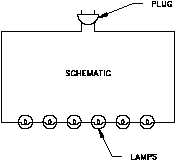
A wiring diagram for parts of an electric guitar showing semi pictorial representation of devices arranged in roughly the same locations they would have in the guitar. It is the most basic type of electrical print.
Electrical Wiring Systems And Methods Of Electrical Wiring
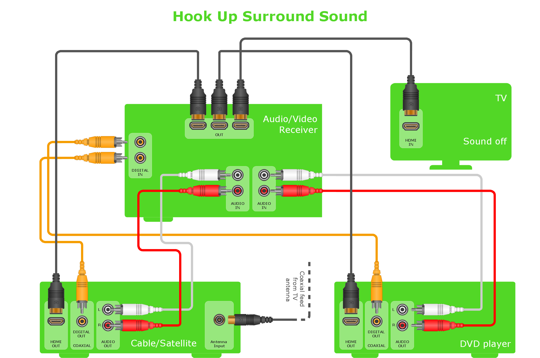
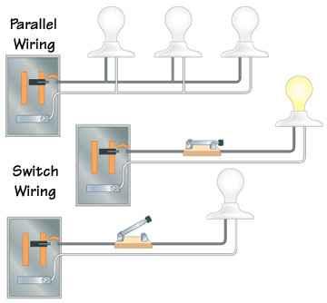
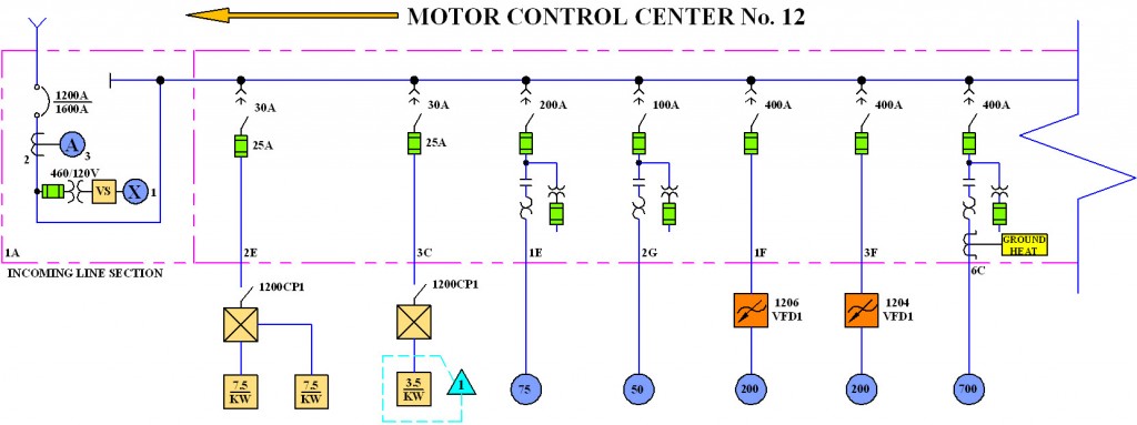
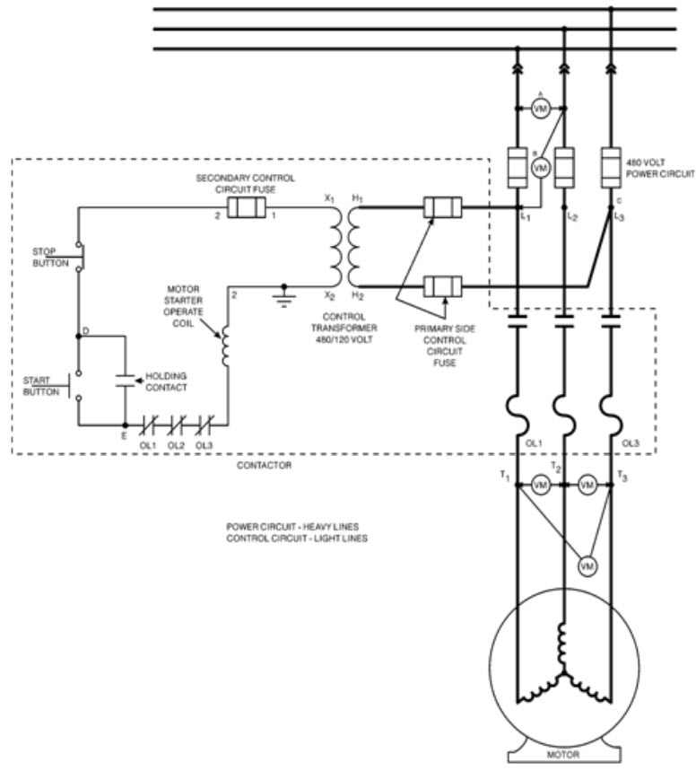
Types of wiring diagram. As the name suggests one line diagrams use a single line to represent all three phases. Wiring diagrams of plc and dcs systems di do ai ao in this article we are sharing the basic concepts of plc and dcs control systems wiring diagrams for digital input di digital output do analog input ai and analog output ao signals. Unlike a schematic its. Majorly the wiring is divided into two types namely parallel wiring and series wiring depending on the way the devices are powered or connected to the supply. The wiring diagram shows the interconnection wiring between the electrical equipment. The outlet should be wired to a dedicated 20 amp240 volt circuit breaker in the service panel using 122 awg cable.
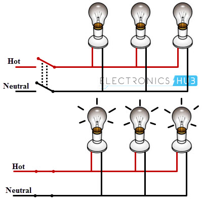
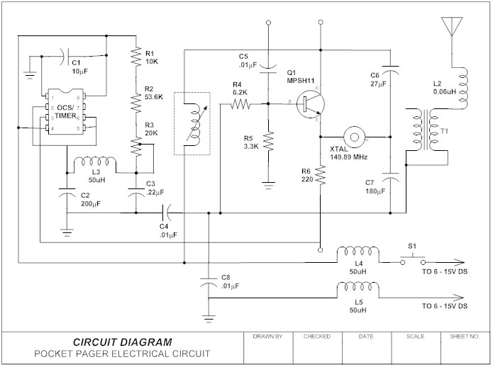
Lead sheathed or metal sheathed wiring. It is the most accepted wiring in homes and industries in which devices are connected in parallel with the supply source as shown in figure. Schematic diagrams schematic electrical wiring diagrams are different from other electrical wiring diagrams because. In parallel wiring several devices on the installation are powered on a single circuit. Wiring diagram a wiring diagram is the most common form of the electrical wiring diagram. Cts or trs or pvc sheath wiring.
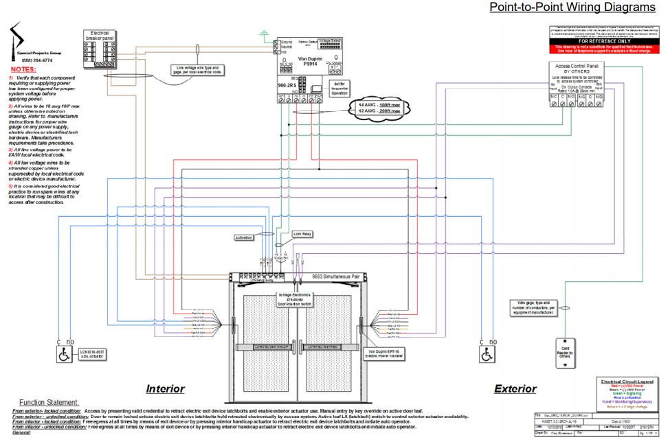
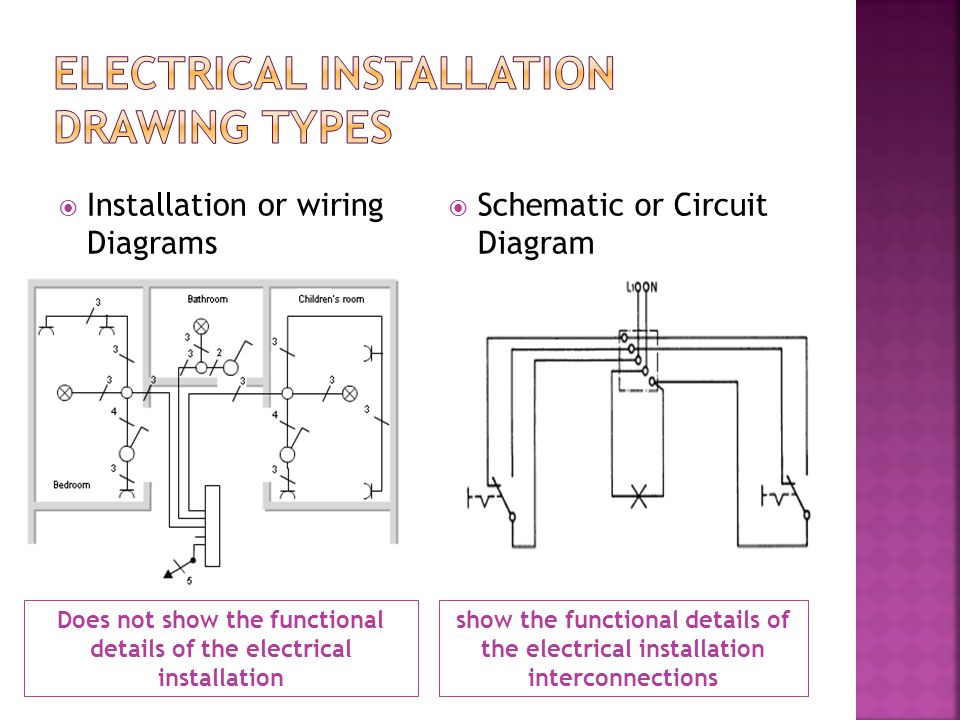
These diagrams show the functional apparatus at their appropriate relative physical locations. These details may not be so easily found on a more schematic drawing. One line diagrams do not show the exact electrical connections of the circuits. Wooden casing and capping wiring. With this wiring both the black and white wires are used to carry 120 volts each and the white wire is wrapped with electrical tape to label it hot. A one line diagram or single line diagram is a simplified way to represent a three phase power system.
This outlet is commonly used for a heavy load such as a large air conditioner. Complete with a color coded trailer wiring diagram for each plug type this guide walks through various trailer wiring installation solution including custom wiring splice in wiring and replacement wiring. Different types of electrical wiring systems. If your vehicle is not equipped with a working trailer wiring harness there are a number of different solutions to provide the perfect fit for your specific vehicle. Wiring a 20 amp 240 volt appliance receptacle. Lines are used to represent a single carrier multiple conductors installed in the same channel are shown as a single line with radial branches and the conductors.
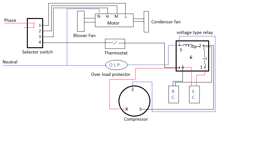
An automotive wiring diagram showing useful information such as crimp connection locations and wire colors.
Gallery of Types Of Wiring Diagram