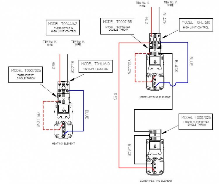
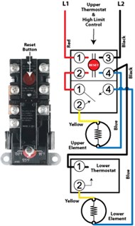
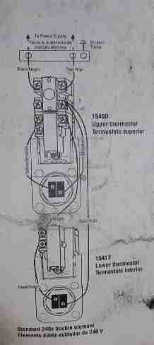
If old upper thermostat is a robertshaw control wire new upper thermostat per figure 2 noting that the physical location of the 2 and the 4 terminals are reversed for the new upper thermostat. Yellow the yellow wire connects to your compressor.
Page 9 Electrical Technology
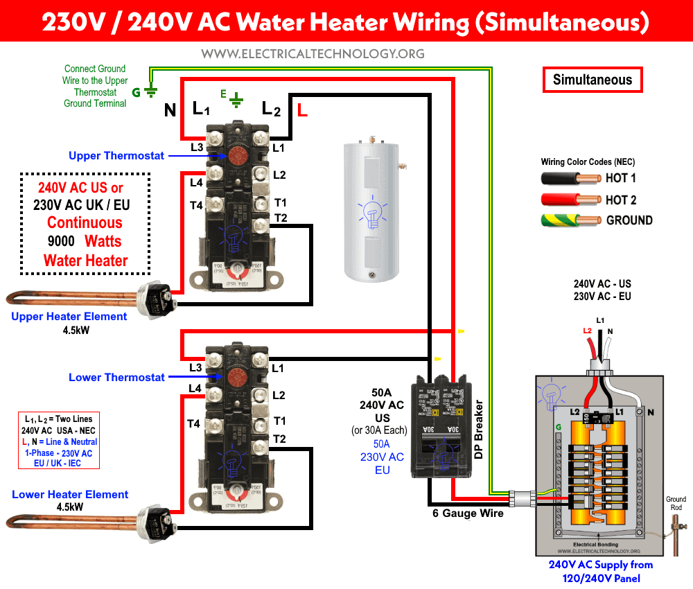
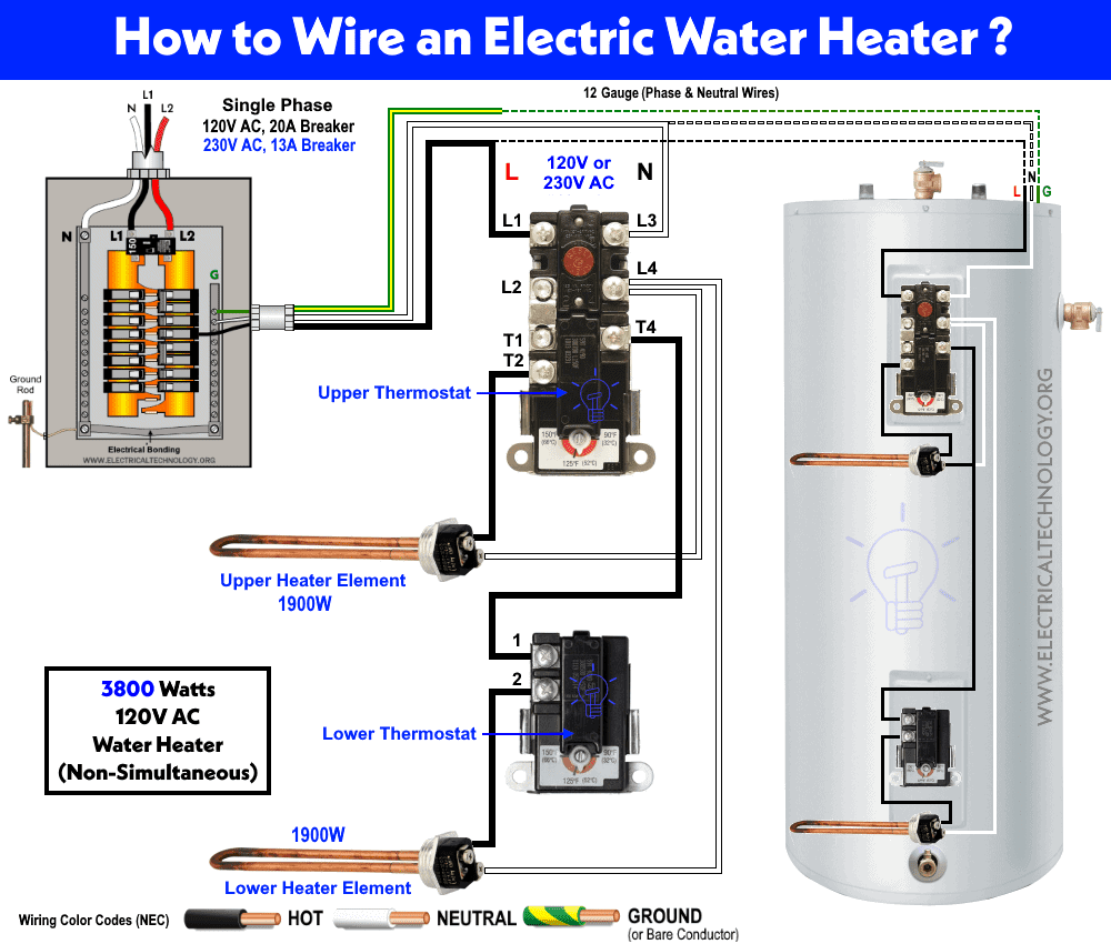
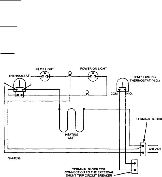
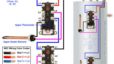
Upper thermostat wiring diagram. White the white wire is what connects to the auxiliary heat on your system. The line is connected to the l 1 terminal while neutral or second line is connected to the l 3 terminal. The rh wire connects to the heating system. The yellow wire connects to your compressor. Both lines from the main db as power supply is connected to the thermostats and heating elements. Wiring diagrams therm o disc thermostats type 59t single element double element simultaneous operation double element.
The white wire connects to your heat. The rc wire connects to the cooling system. Note that the wire indicated by the. As i shown in the below electric water heater wiring diagram. The water heater element is connected to the thermostat via t 2 as hot and l 4 as neutral. Rc red wire power 24 vac rh or 4 red wire jumpered power 24 vac.
Collection of wiring diagram for hot water heater thermostat. The same power supply is connected to the lower thermostat and heating element following by the same circuit breaker and switch. Upper thermostat high temp. The wiring connection for both single phase 120v and 240v are same ie. L 1 is connected to the left side of both upper thermostat and lower thermostat l 3 via 50 amperes circuit breaker and 45 amperes switch. Black color is neutral while red is phase or line and the yellowgreen wire is used for ground earth.
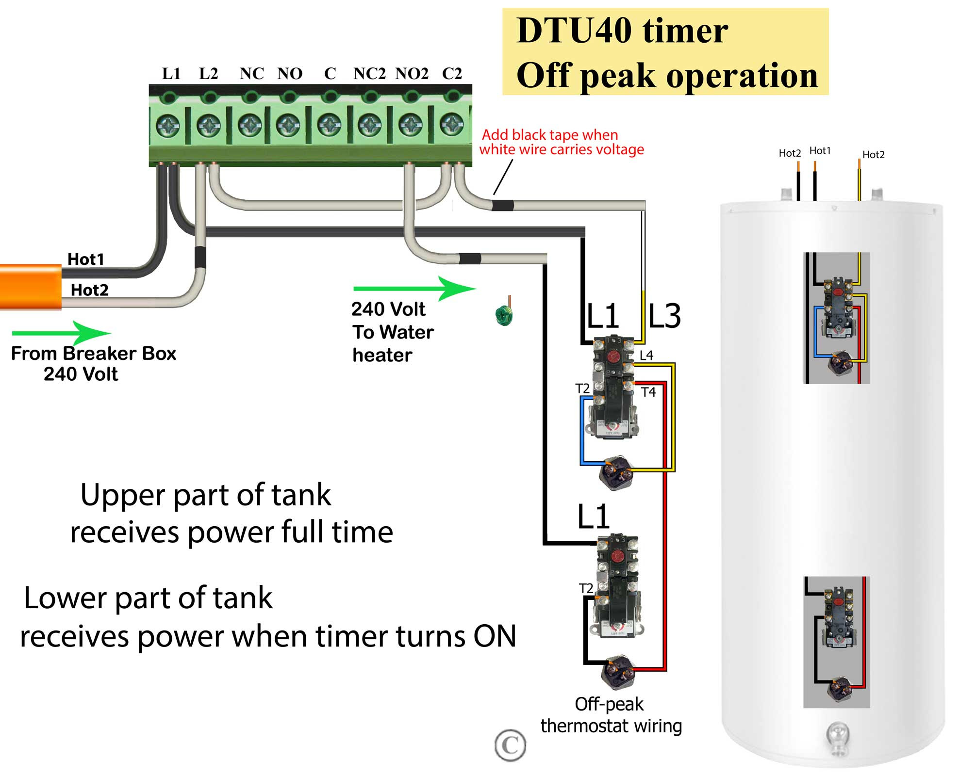
The diagram below shows how a basic 4 wire thermostat is connected as indicated by the color code chart above. The basic heat ac system thermostat typically utilizes only 5 terminals. This wire connects to your heat pump if applicable. Here is the industry standard thermostat wire color code used for most systems. When upper water heater element done his work upper thermostat switch of the neutral wire to upper thermostat and provide the neutral wire to lower thermostat. The green wire connects to the fan.
Limit eco upper heating element yellow black l1 junction red 1 3 1 2 black red lower thermostat 1 2 4 branch circuit to electrical. Green the green wire connects to the fan. If old thermostat has 8 terminals as in figure 6 wire new 7 terminal thermostat per figure 5. It shows the elements of the circuit as simplified forms and also the power as well as signal connections between the tools. A wiring diagram is a simplified standard pictorial representation of an electrical circuit.
Gallery of Upper Thermostat Wiring Diagram