Without the use of the switch the water pump would always be on or off. However with the pressure switch the pump can be adjusted to turn on and off at predetermined settings to control the pump and subsequent pressure.
Rainflo 75 Hp Universal Rainwater Pump
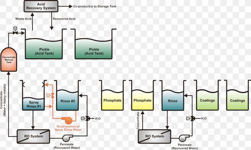
Water pump wiring diagram. This article describes troubleshooting a submersible well pump that was causing tripped circuit breakers and that pumped water only at a slow reduced rate and pressure. Well pump wiring diagnosis repair. Ultimately using some simple electrical tests the homeowner traced the water pump problems to a nicked well pump wiring circuit wire. Otherwise the structure wont work as it should be. Shurflo water pump wiring diagram rv water pump switch wiring diagram rv water pump wiring diagram shurflo 12v water pump wiring diagram every electric arrangement consists of various unique components. Collection of 3 wire submersible pump wiring diagram.
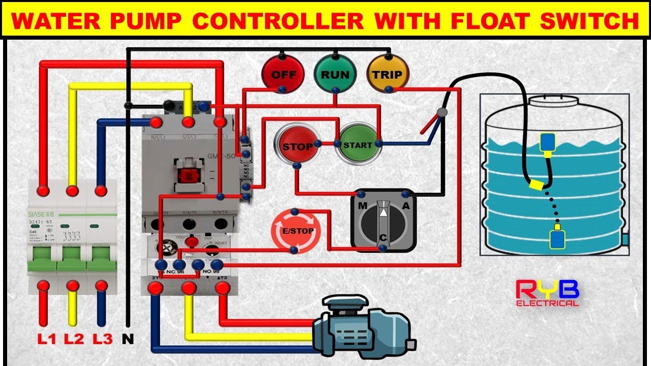
Each part should be placed and connected with other parts in particular way. Pressure switches are used on water pumps for the accurate control of the pump as it produces pressurized water. To read a wiring diagram initially you have to recognize just what essential aspects are consisted of in a wiring diagram and also which photographic icons are used to represent them. After determining the voltage is zero disconnect the motor wires directly from the pressure switch box m1 and m2. Related queries float switch wiring diagram float switch wiring connection float switch connection with contactor float switch ka connection kaise kare contactor connection with float switch. It shows the elements of the circuit as simplified forms and also the power as well as signal links between the devices.
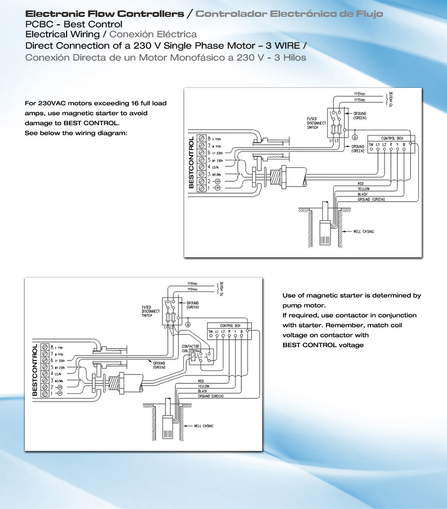
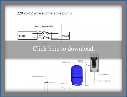
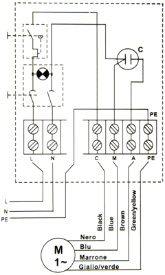
A wiring diagram is a streamlined standard photographic depiction of an electric circuit. The diagrams for both the two and three wire pumps can be downloaded using adobe. Variety of water pump pressure switch wiring diagram. The typical elements in a wiring diagram are ground power supply wire as well as connection output tools switches resistors reasoning gateway lights etc. Single phase wiring diagrams single phase wiring diagram for 05hp pumps with governor switch single phase wiring diagram with governor switch single phase wiring diagram without governor switch three phase wiring diagrams three phase 208v wiring diagram three phase 230v wiring diagram three phase 460v wiring diagram three phase 575v wiring diagram kb pump wiring diagrams kb pump 230v wiring. The green ground wire should also be terminated to the box and a ground coming from the panel.
To replace the two wire pump. Each part should be placed and connected with other parts in particular way. It reveals the elements of the circuit as streamlined forms as well as the power and also signal connections in between the devices. If not the structure wont work as it should be. Water pump pressure switch wiring diagram square d water pump pressure switch wiring diagram water pump pressure control switch wiring diagram water pump pressure switch wiring diagram every electrical structure is composed of various different components. A wiring diagram is a streamlined traditional photographic representation of an electrical circuit.
Gallery of Water Pump Wiring Diagram