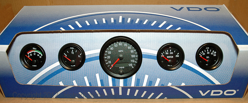
Temperature gauge pressure gauge rudder angel gauge trim gauge fuel gauge fresh water gauge for level type sensor. If you have additional questions please contact vdo.
Vdo Oil Pressure Amp Temp Gauge Part 1
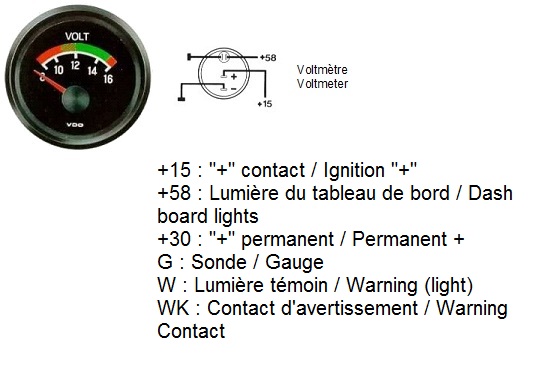
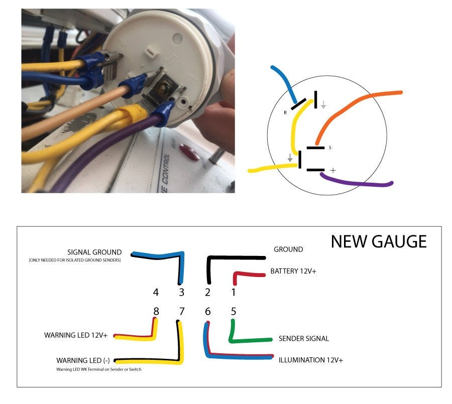
Vdo gauge wiring diagram. Only connect cables according to the electrical wiring diagram. According to the electrical wiring diagram. Consequently you may not modify or manipulate the product. Welcome to the vdo catalog for auto enthusiast gauges and accessories. Diagram a gauge dimensions configuring the vdo tachometer. Vdo spin lok clamp or mounting bracket 1 5.
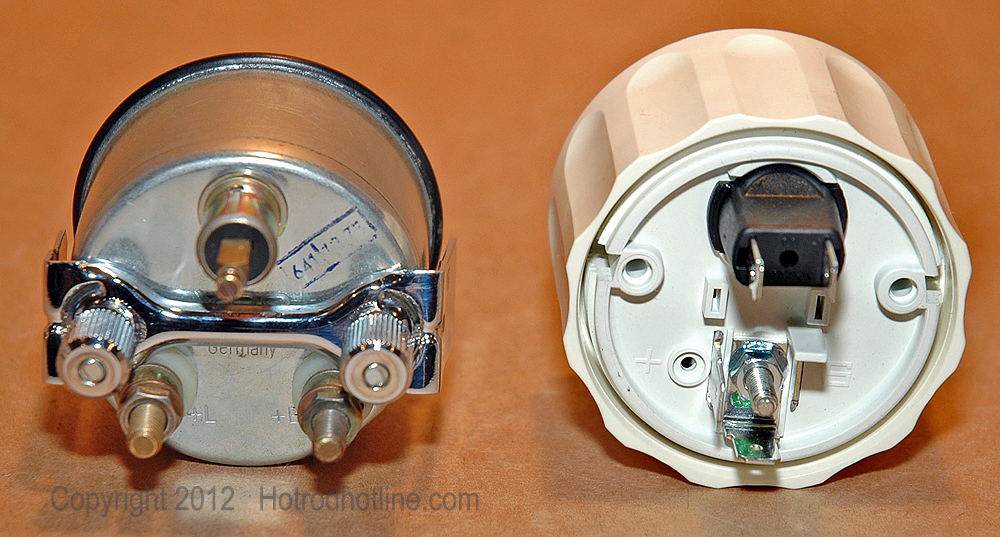
Modifications or manipulations to vdo products can affect safety. Installation instructions 1 caution. Junction and attach the wire from the speedometer. The final ground run using 14 gauge wire should be connected to a good. Repair service for oem instrument clusters and systems merri mcintyre phone. 310 936 300f 150c gear temperature gauge use with vdo sender 12v 250 spade connection learn more.
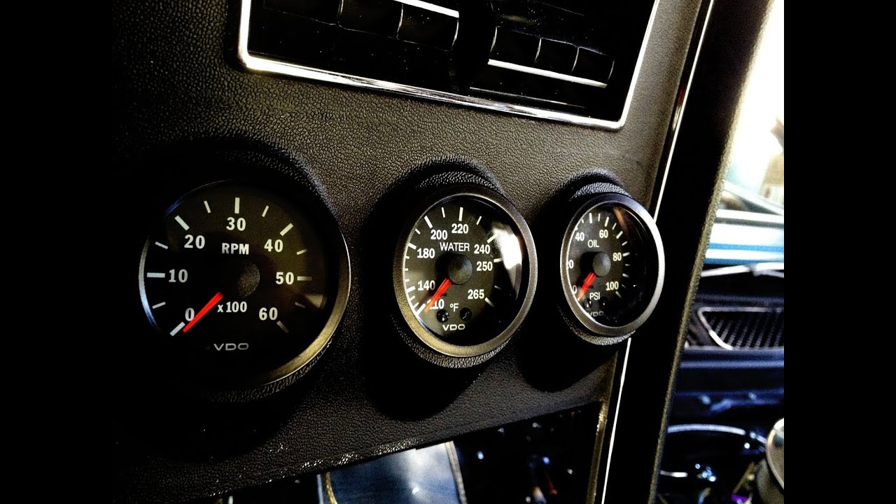
Wire gauges in series from a positive accessory to a source which is not already overloaded with fans air conditioning and such. We continue to work to deliver the functionality durability and high quality finish that have earned our products a best in class reputation worldwide. If operating the instrument on power. Temperature pressure or fuel gauge 2⁵₈ 66 mm diameter 1 2. Lamp socket push in wedge type 1 3. Since 1920 weve been focused on providing our customers with the best possible instrumentation.
0 electronic speedometer hall effect sender installation instructions and wiring diagram 7udqvplvvlrq type a speedometer 4 wire system 57. Standard resistive gauges 52mm 1224 volt retrofit kit temperature pressure level trim 2013 viewline 52mm wiring diagram 2014 viewline level gauges 1224 volt 2011 viewline level gauges 52mm 2008 viewline pitot speedometer level gauge 2011 viewline pitot speedometerfuel gauge 110mm 2011. Read these instructions thoroughly before making installation. The ground œ wire is also run in series including the light socket ground. Refer to the wiring diagram diagram g. 158 or equivalent 1 4.
Refer to diagram d for the proper wiring of the speedometer. Diagram c shows how to set the switches for diagram d with alternator use this table to calculate pulsesrevolution set switches. Aftermarket technical support troubleshooting. Do not deviate from assembly or. Before the tachometer will function prop erly with your engine you will need to set the switches as shown in diagrams c or d. Light bulb 12 volt ge.
Repair service for aftermarket gauges and accessories connie heflin phone.
Gallery of Vdo Gauge Wiring Diagram