Wall switch wiring diagram. Wire wall lights to a ceiling light power supply.

Light Switch Wikipedia
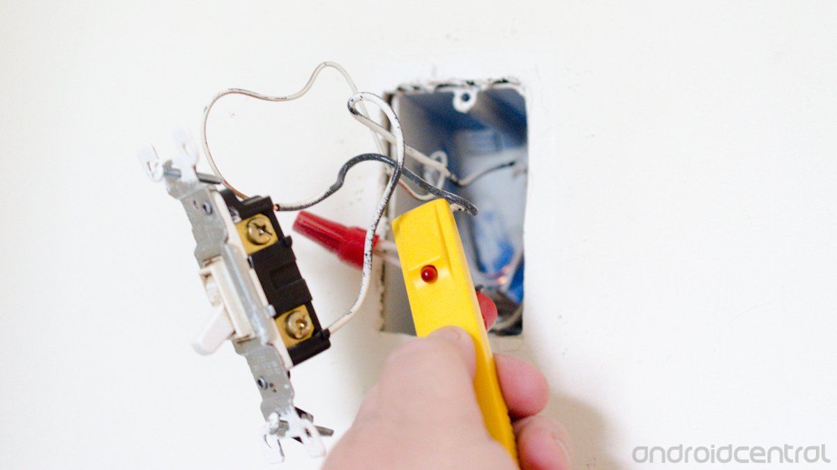
Wall light wiring diagram uk. Advantages of adding a wall light. Adding a wall light to a room can have a number of advantages. A flush fitting wall box is sunk into the wall to take the switch or alternatively a surface mounted box is fitted. The black wire power in source attaches to one of the switch screw terminals. You simply need to run the spur cable from this power supply point to a new junction box in the ceiling void. If this is not evident with a mains tester screwdriver and turning the electrical supply back on by probing either side of the switch where the wires are connected and secured with small brass screws ascertain which side of the switch is the live feed wire.
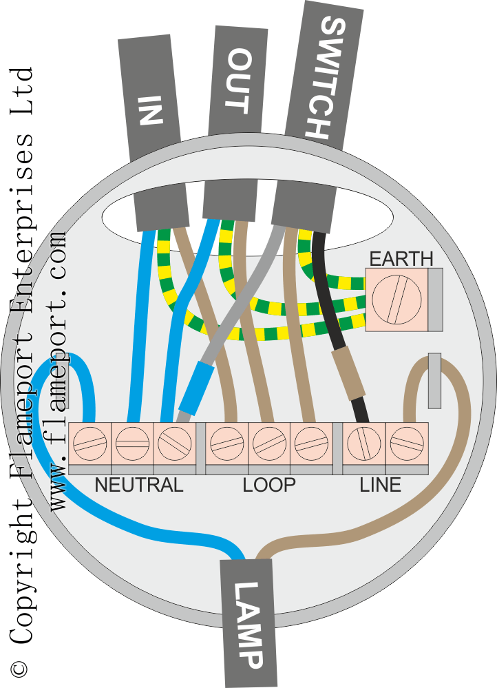
Circuit electrical wiring enters the switch box. The cable that brings power to your wall lights is a spur cable. This is an alternative way of wiring a lighting circuit. Instead of taking the feed wire from the consumer unit to the ceiling rose it is taken to the switch. Explanation of wiring diagram 1. The neutrals are connected together using a terminal connector.
The light can be switched independently of the main lights in the room which means it can serve as a night light above the bed a reading light in the bedroom a hall light which can be operated from somewhere other than the hall an outside light operated from indoors a reading. It can originate from a ceiling rose or lighting circuit junction box. The permanent live wire is wired into the switch and the switched live into the switched live terminal. Switch wiring shows the power source power in starts at the switch box. Most room lights are controlled by wall mounted toggle switches although alternatively touch sensitive or rotary light dimmers can be fitted the cable normally runs down the wall within conduit within the plaster. Featuring wiring diagrams for single pole wall switches commonly used in the home.
Gallery of Wall Light Wiring Diagram Uk