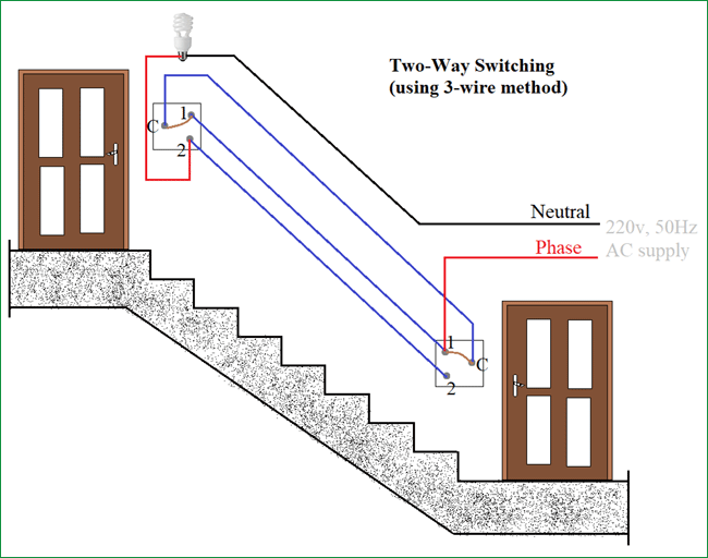
Section 2 field wiring 50 wiring the a5000gec 24vdc zero speed switch 51 power connections and relay connections to the a5000gec 24vdc zero speed switch are shown on figure 3 page 4. This diagram illustrates wiring for one switch to control 2 or more lights.
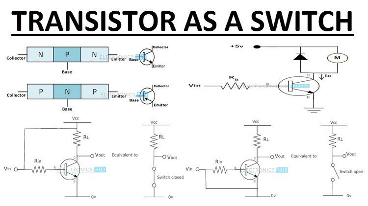
Working Of Transistor As A Switch Npn And Pnp Transistors
Zero speed switch wiring diagram. Zero speed switch wiring diagram. Multiple light wiring diagram. The source is at sw1 and 2 wire cable runs from there to the fixtures. Collection of john deere lawn mower wiring diagram. The hot and neutral terminals on each fixture are spliced with a pigtail to the circuit wires which then continue on to the next light. Also figure 4 5 page 5 6 show typical wiring diagrams.
Click on the image to enlarge and then save it to your computer by. Zero speed switches zss also known as speed actuating sensing switches are used to detect the stoppage or unacceptably slow movement of a rotating shaft. Connect the equipment safety ground to the. 52 connect 24 vdc to l1 red and l2 white. Wiring diagrams do not show the. Generally its applications are in various machines conveyors power plants and industries involving the production of cement sugar textiles paper etc.
Zero speed switch l2n zero speed switch zero speed switch typical wiring 115230 v ac 5060 hz should the time delay feature on start up not be required power should be applied continuously from a separate source. Typically this would be desirable for automatic up stream start up of conveying devices after down stream drive has reached its. The simplest approach to read a home wiring diagram is to begin at the source or the major power supply. Sometimes wiring diagram may also refer to the architectural wiring program. John deere lawn mower wiring diagram john deere 318 ignition switch wiring diagram valid john deere ignition switch wiring diagram collection. They are operated by a toggle lever mounted on the front of the switch.
The wiring diagram on the opposite hand is particularly beneficial to an outside electrician. Wiring diagrams m c w bulletin 600 bulletin 600 manual starting switches are designed for starting and protecting small ac and dc motors rated at 1 hp or less where undervoltage protection is not needed.
Gallery of Zero Speed Switch Wiring Diagram