Through the different wiring diagrams below. This article describes how to wire up heating zone valves.

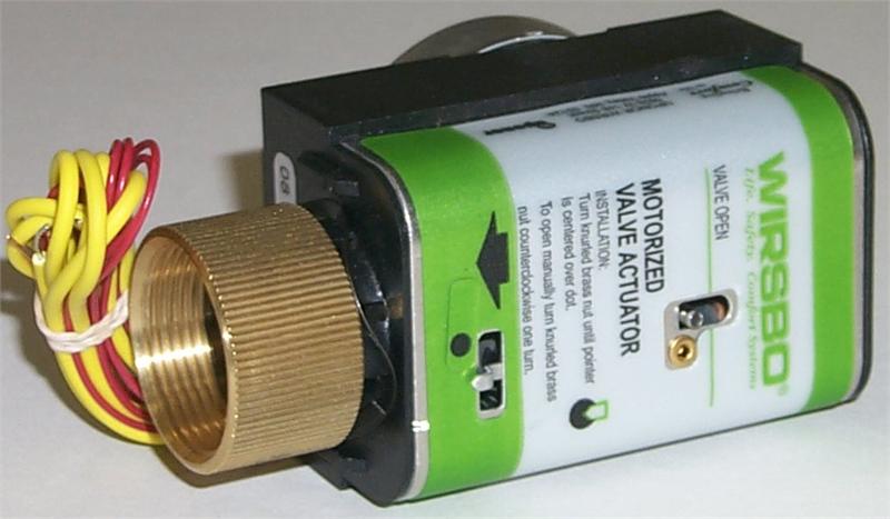
Electrical Actuators Vanco Flow Control
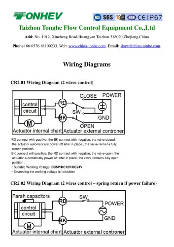
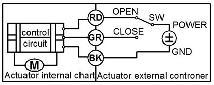
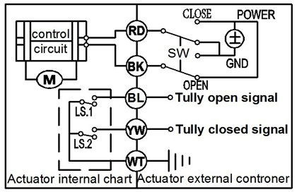
Actuator valve wiring diagram. If the pop up blocker is turned on in your browser you are not able to view the wiring diagram. Motor operated valve wiring diagram can be a variety of can be 2 lines 3 lines 4 lines can also be connected with a feedback signal line 2 lines can also be with ground wire. A wiring diagram is a simplified standard photographic representation of an electrical circuit. They are divided into active switch type passive switch type potentiometer type and regulation type according to the control mode. A wiring diagram is a simplified conventional photographic representation of an electrical circuit. Wiring diagram number quotation number.
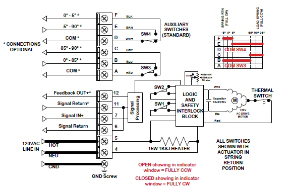
It shows the components of the circuit as simplified shapes and the capacity and signal contacts along with the devices. We include wiring diagrams and installation instructions for most zone valve model and multi zone controllers and we describe special wiring problems that can occur if you mix different types brands or models of heating zone valves on the same hydronic heating hot water heating system. The wiring diagram opens in a pop up window. Wiring diversification according to the customer equipment voltage is different line number is different provide different wiring mode. Rotork valve actuator wiring diagram pub002 004 00 0813 screw thermostat rotork valve actuator wiring diagram wiring diagram is a simplified customary pictorial representation of an electrical circuit. Selected wiring diagrams under documents attention.
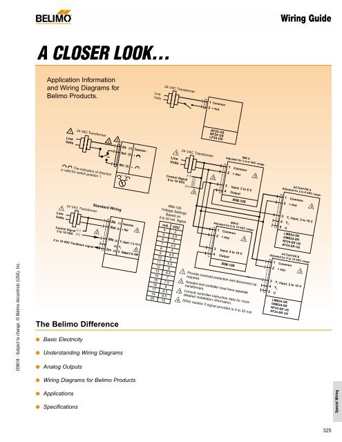
Zone valve wiring diagrams boiler wiring diagrams wiring f or 4 wire zone valve low voltage 120 volts 120v 24v boiler connections t 1 t 2 3 zone valve hot neutral. Hot water heating system zone valve installation. It reveals the components of the circuit as streamlined forms and the power and signal connections between the tools. These 2 way 3 way and 4 way solenoid valves can handle most fluid control applications and are now available with class i division 2 approvals we also offer a complete line of general service isolation pinch proportional valves and manifold assemblies for use in medical equipment analytical instrumentation and industrial applications. It shows the parts of the circuit as simplified forms as well as the power and also signal links between the tools. Variety of honeywell actuator wiring diagram.
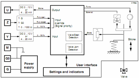
Electric valve actuators can be divided into ac ac110v ac220v ac380v and dc dc24v dc12v according to the power supply voltage. Please enter the address of our website in the address of web site to allow box.
Gallery of Actuator Valve Wiring Diagram


/Page-2497001.png)