Use a wiring diagram for the year model of your vehicle. Find the product you want via the departments which can be found on the top banner or the search facility if you know our part number lucas number or keyword.
Mallory Unlite For A Rover V8
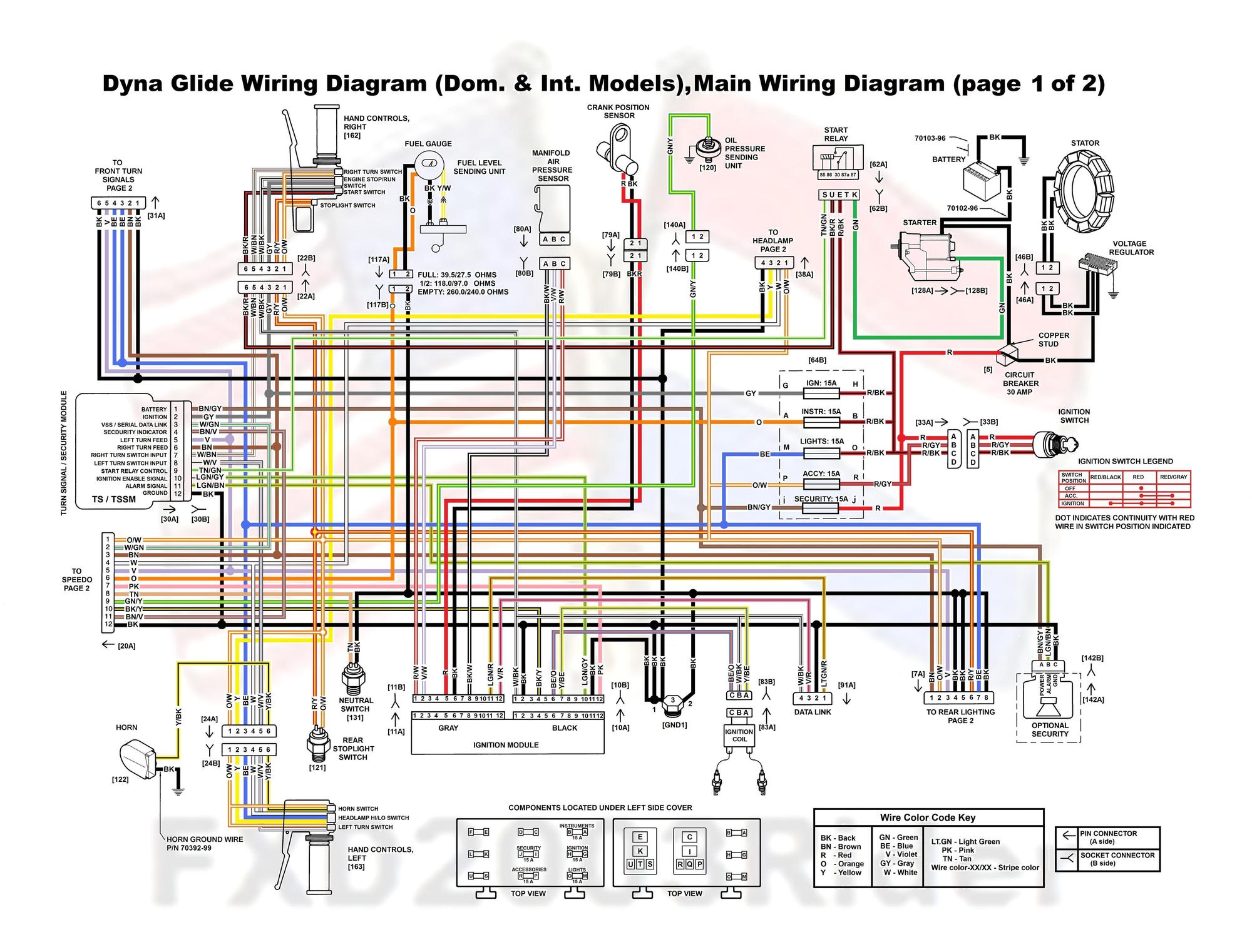
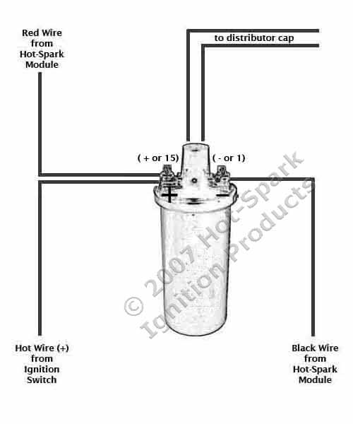
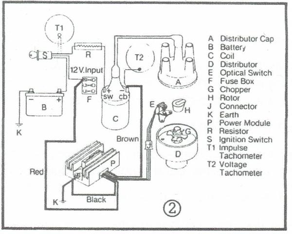
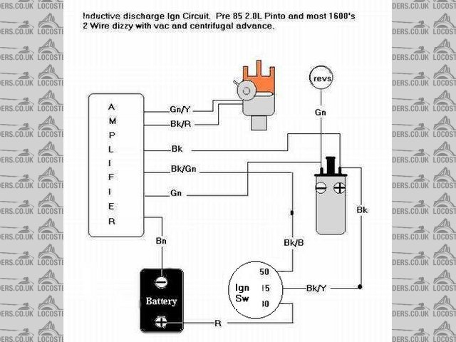
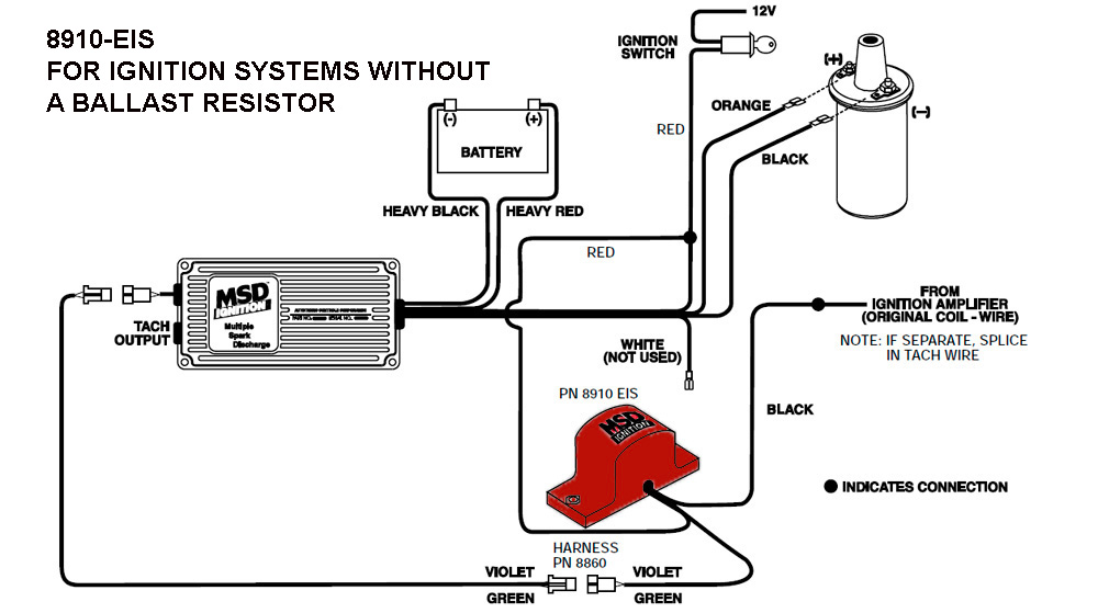
Lumenition ignition wiring diagram. Lumenition optically switched contact breaker replacement ignition systems consist of two basic models the optronic ignition system and the performance ignition system. If so with the power on take the cap off and pull the ht lead to coil out of the cap. Sjp date 110707 ver 23 file pma50 installation v23doc page 3 of 3 3. Referring to illustration 2 connect red wire using extension supplied if necessary to either a feed side of ignition terminal f of fuse box. As for the lumenition first make sure you ve got 12v to the low tension side of the coil. Usually supplied as a power module and optical switch in one pack and a fitting kit designed for your particular distributor the standard optronic is also available as the pmc 50 which includes the.
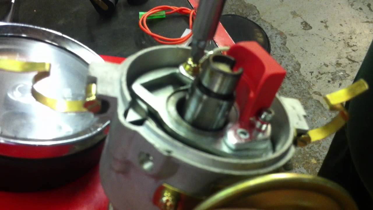
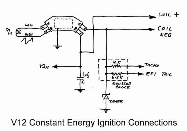
Lumenition optronic ignition system pma50. Its easy to buy our products online. To test the optical switch the optical switch must be connected to a good power module with a sensitive voltmeter measure the voltage between the blue and. Placement of the module varies from model to model so check the appropiate service manual of your vehicle for the exact location. Lumenition optronicâ ignition system auth. Please remember to add the forward slash and not to put in any.
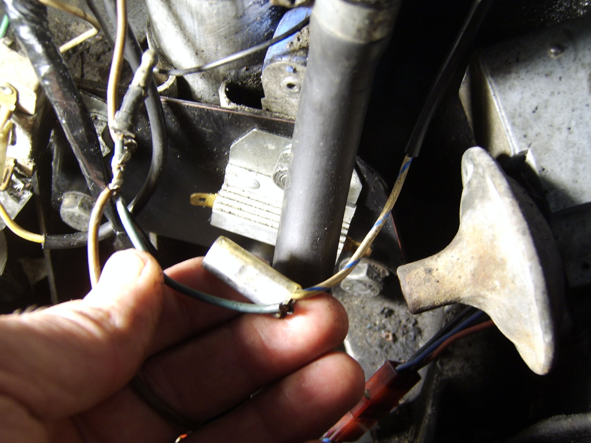
A good source for that is the negative side of the fuel pump inertia cut off switch so that the ignition is cut at the same time as the pump in the event of an accident. Unless they have changed the wiring for lumenition the red wire should be the positive feed from the battery. Use a voltmeter or 12v bulb not exceeding 6w wired between the ignition coil negative terminal and earth see illustration 4. Lumenition optronic ignition system pma 50 power module auth. Locate the terminals running into and out of the ignition module. The installation of both systems is straight forward and easily reversible involves no specialist tools.
Sjpearce date 111202 ver 22 file pma50 installation page 3 of 6 please note that the brown wire is a violet wire on later units. Pooh you cant assume black is ground get a wiring diagram. Turn engine and align timing marks making sure the rotor tip is pointing to the ht pick up segment in the distributor cap of the recommended firing plug normally no1. The recommended ignition coils are the lumenition megaspark 4 coil and ballast resistor combination or the megaspark 6 unballasted 3 ohm coil. Lumenition ignition system description lumenition optically switched contact breaker replacement ignition systems consist of two basic models the optronic ignition system and the performance ignition system.
Gallery of Lumenition Ignition Wiring Diagram