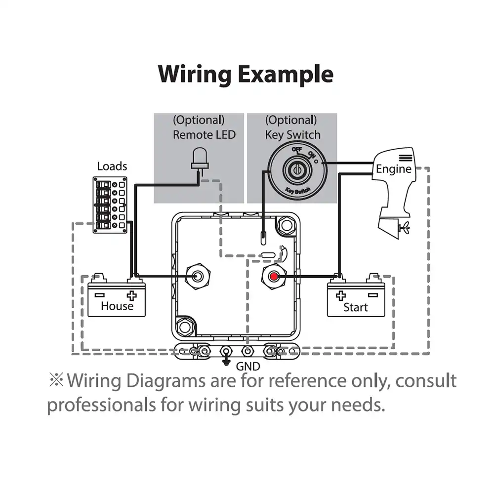
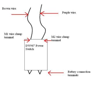
Vsr 8 8 dn200 8625 2191 0148 376 0322 818 0248 63 0177 45 do not trim the paddle. 2 3 connect the thin black earth wire from the vsr to the vehicle chassis or the starter batterys negative.

Re Alternate Battery Wiring With Vsr And Switch E Nation
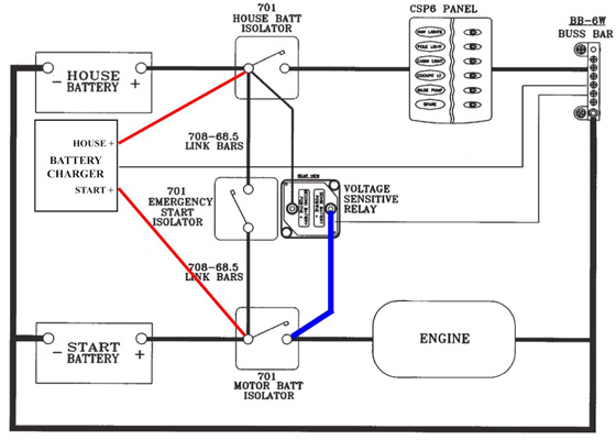
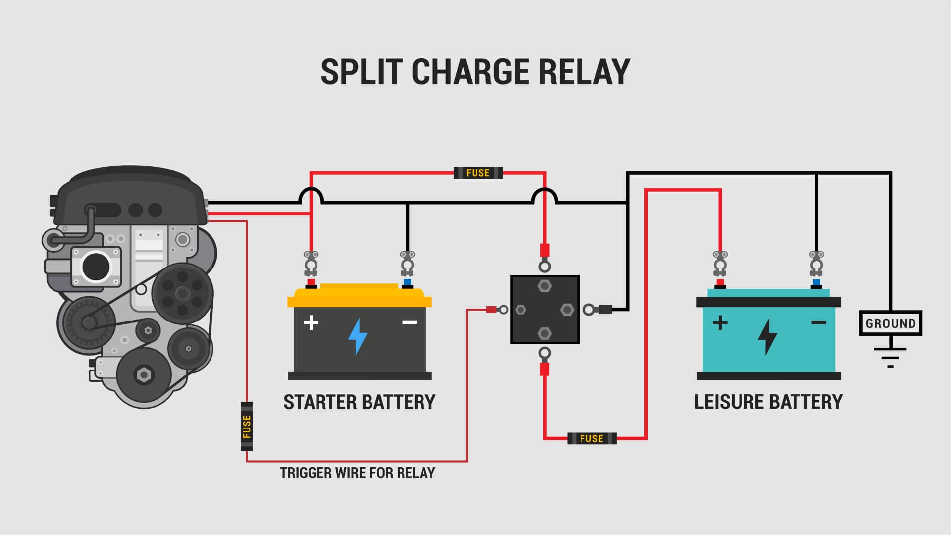
Vsr wiring diagram. The model vsr is a vane type waterflow switch for use on wet sprinkler systems. The vsr will not work properly. How the vsr works once the starting batterys voltage rises to above 37 vdc the vsr switches to charge both batteries in parallel when the voltage drops below 28 v dc the vsr disengages. In this image we are looking at the guts of a combinervsr that was 7 years old. I have misplaced the diagram i had when i first installed the system when i had the johnson dec 02 12 volt relay wiring diagrams durite vsr split charge relays 12v having completed the camper interior of the van it was time to hook up a second battery to provide power in the back of the van. Break out thin section of cover when wiring both switches from one.
A buzzer like sound can be heard as the relay quickly switches in and out. The model vsr is a vane type waterflow switch with non corrosive insert for use on wet sprinkler systems. This video shows what a voltage sensitive relay or vsr is and how to install one in a dual battery setup to make sure both batteries get charged but only one can go flat. 4 connect the positive ring terminal of the included long cable to the unmarked silver terminal of the vsr. I have misplaced the diagram i had when i first installed the system when i had the 1984 johnson 70. See ordering information chart.
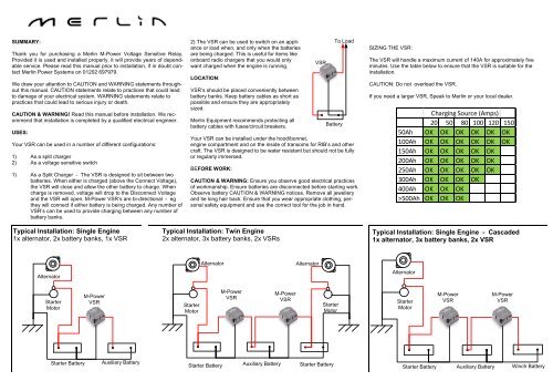
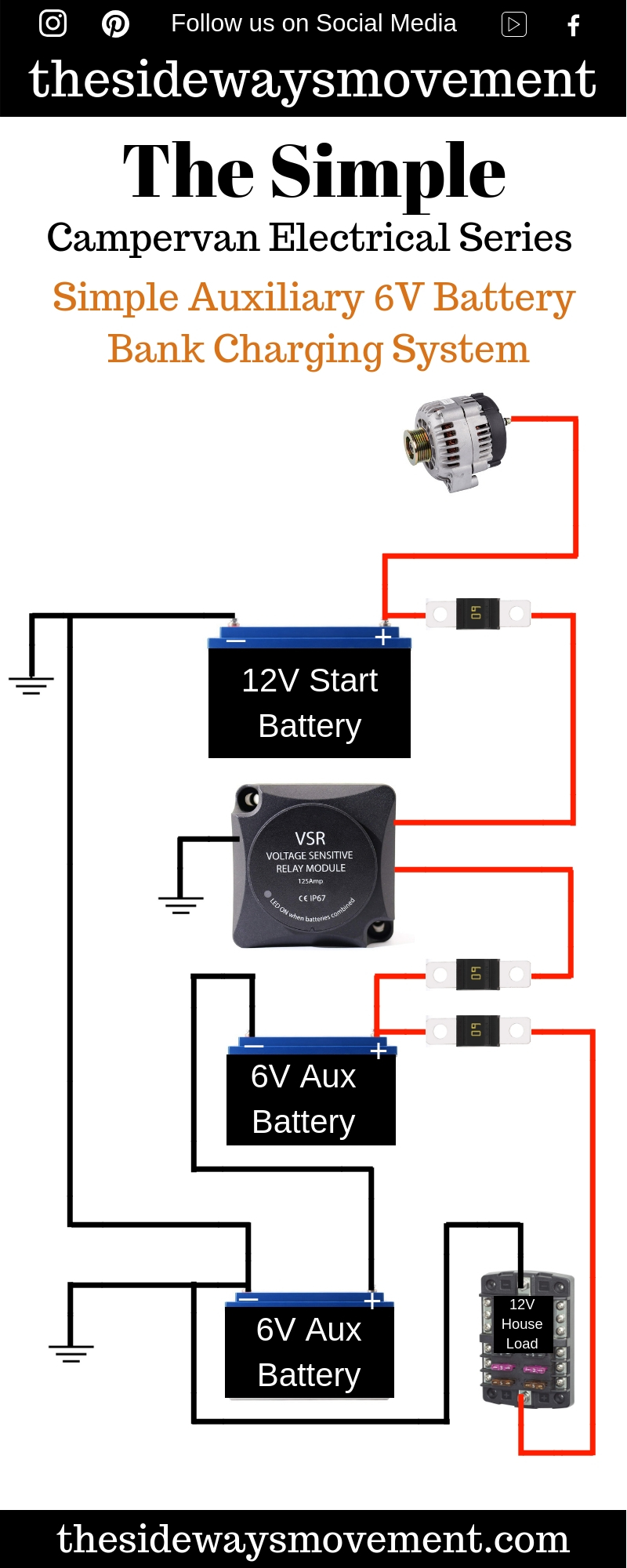
Wiringthis is without doubt where many people get it wrong and end up with a system that may work but barely and nowhere near as well as it could and should doing it right can double the usable capacity of your auxiliary batteries over and above what many people normally have and it will also help them charge much faster and in turn they will last longer too. It is ul the switches are actuated when a flow of 10 gpm 38 lpm or more occurs. Do not obstruct or otherwise prevent. Wiring both switches from one conduit. Schedules 10 through 40 sizes 2 thru 8 50 mm thru 200 mm and schedule 5 sizes 2 thru 6. Lpc approved sizes are 2 thru 8 50 mm thru 200 mm.
Potter vsr flow switch wiring diagram. It is nothing more than an electronic switch that is closed or opened using a relay coil. Failure to follow these instructions may prevent the device from operating and will void the warranty. Could you be kind enough to send me a wiring diagram so i can correctly connect the vsr relay and guest switch for the 2011 e tech 90 engine. The wiring cabling. A relay is the control device used inside a combiner vsr or acr.
It is ul listed and fm approved for use on steel pipe. Connect the negative wire of the long cable to the negative wire coming from the start battery. By energizing or de energizing the coil the relay can change positions from open to closed or closed to open.
Gallery of Vsr Wiring Diagram