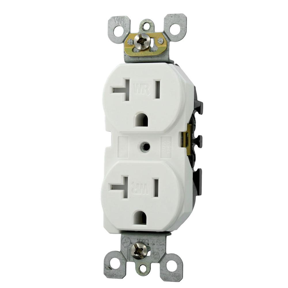
A grounded contact at the bottom center is crescent shaped. Assortment of duplex pump control panel wiring diagram.
Understanding Rs485 Wiring Connection Monitoring Software
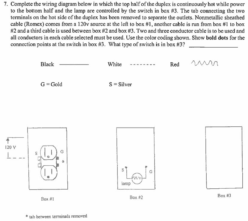
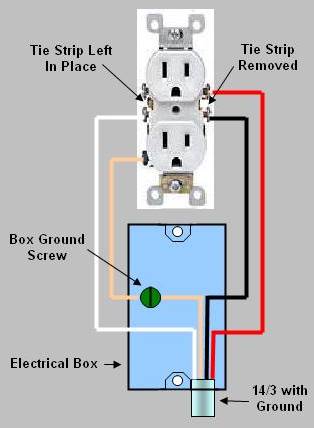
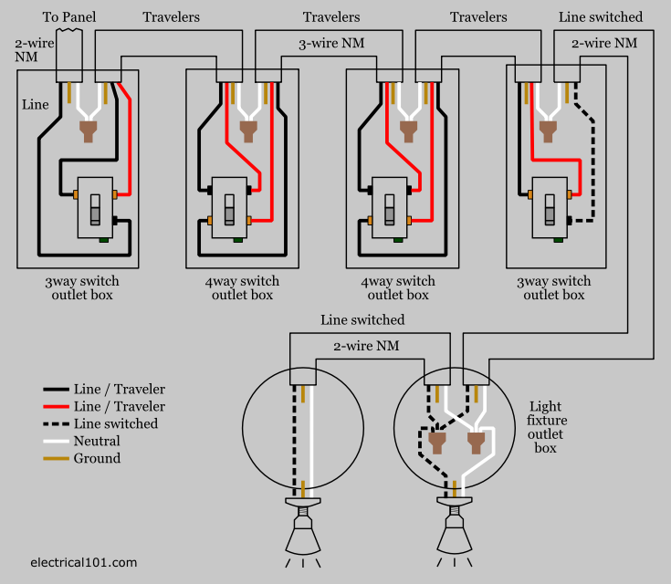
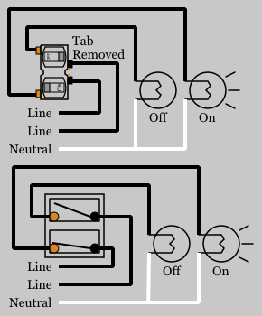
Duplex wiring diagram. My light switch wiring diagrams may be helpful to you. They can be used for ceiling fans where one switch controls the fan and the other switch controls the light kit. Single pole duplex switch diagrams. Also shown is the half of the receptacle that is live at all times and the tab that must be cut in order to split the receptacles. Single pole duplex switches. In this diagram two duplex receptacle outlets are installed in the same box and wired separately to the source using pigtails spliced to connect the terminals of each one.
A wiring diagram is a streamlined standard photographic representation of an electric circuit. A single pole duplex switch contains two single pole switches. It shows the elements of the circuit as simplified forms as well as the power as well as signal links in between the gadgets. Dont use this receptacle when no ground wire is available. Duplex switches can replace a single switch without expanding the switch box. With each outlet connected by its own pigtail wire if one fails because of physical damage the other wont be affected and should still work.
The long slot on the left is the neutral contact and the short slot is the hot contact. Wiring dual outlets in a series. Uinfratechcontrolsduplex switch 85 x 11 1 author. This is a standard 15 amp 120 volt wall receptacle outlet wiring diagram. This is a polarized device. Wiring a grounded duplex receptacle outlet.
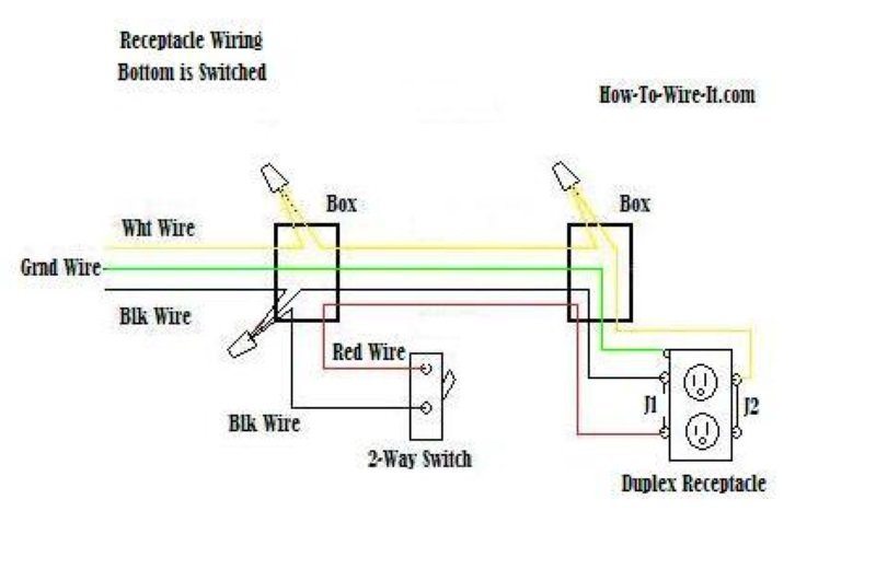
Depicted here is the wiring diagram for controlling the half of two duplex electrical receptacles by a wall switch without a neutral conductor.
Gallery of Duplex Wiring Diagram